In the world of smart homes, there are plenty of fantastic devices out there that can integrate well with Home Assistant and your other tools, and while dedicated sensors are great for their simplicity and ease of use, costs can quickly rack up, and it can be far cheaper to build your own devices once you feel comfortable. While that’s true for sensors, the savings can be exponential with more complicated hardware… and that’s where this beautiful LED matrix display comes in.
There are plenty of LED-based displays out there like this one, but the problem is that many of them are proprietary, may not support your own self-hosted solutions, or may even come with a remote that allows for only setting predefined images or text. You can build something cheaper and more customizable with an ESP32 or a Raspberry Pi, and that’s what I did. It’s beautiful, it’s easy, and incredibly versatile.
If you want to get started, I’ll be linking my GitHub repository at the bottom of this article, with code for both the ESP32 and what I used on the Raspberry Pi 1 Model B+.
Picking your parts and building your own LED matrix
You can use a Raspberry Pi or an ESP32

First and foremost, picking your microcontroller is incredibly important. I’ve been primarily using the ESP32, and while there are ESPHome libraries out there that you can use, you’re better off using either the Arduino IDE or PlatformIO in VS Code. This has a few advantages, primarily in memory usage. As the ESP32 has a “direct memory access” (DMA) mode, pixel data is sent without any involvement from the CPU, so while an ESP32 may seem weaker on the surface, it will perform better than an older Raspberry Pi in many cases. This comes at the cost of RAM, and we need every bit that we can get, hence why it’s good to get away from ESPHome in this instance if you can help it.
However, there is one upside to the Raspberry Pi, and that’s community support. In my research and building my own software for this panel, I found a lot of code examples driving a HUB75 from a Raspberry Pi, complete with example code and even a full API that you can incorporate in Python. My Raspberry Pi is the very first Model B+, with a 700 MHz CPU and just 512 MB RAM. Unfortunately, the overheads associated with Python meant that I couldn’t use it effectively, though newer Pi models definitely can. To give you an idea of how constrained this setup was, when running code that I wrote and the example code given in the much more memory-friendly C++, it would still struggle. I couldn’t open a new SSH session, and SFTP would time out… and that’s after I overclocked the CPU to 800 MHz. As I’ll demonstrate later, I utilized MQTT and Home Assistant to pass data over the network, as anything more than that would be enough to functionally overload the Pi’s CPU.
As a result, if you have a modern Raspberry Pi, the rpi-rgb-led-matrix API is perfect for this kind of project. If you have an underpowered one like I do, then you may run into roadblocks caused by the weaker CPU, and you won’t be able to use the Python API for controlling it. As well, keep in mind that the Raspberry Pi 5 is not supported at this time. If, however, you have an ESP32, you’ll be able to drive this panel with some work as well.

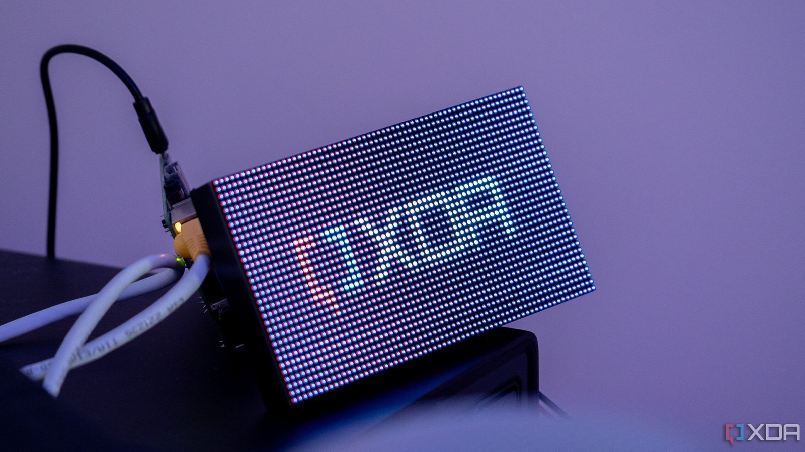
When it comes to picking an LED matrix display, there are countless options out there. These vary in size, pixels, pitch (distance between pixels), and device maker. To keep things simple, I went for the Waveshare RGB P2.5 64×32 LED matrix, which can be a little bit more expensive than alternatives, but those alternatives also come from lesser-known companies, may change the address lines, and can use a different panel chipset. It’s a known quantity, and nearly all of the ESP32 and Raspberry Pi examples that I’ve tested have been able to understand it right out of the box.
This particular panel, like many others, uses a HUB75 interface, and, thankfully, there’s already a lot of documentation out there for wiring up an ESP32 or Raspberry Pi to control it. Keep in mind that these panels are multiplexed, meaning only a specific number of pixels can be turned on at a time, and require using hardware fast enough to iterate through each row. The alternative would be to have pins for each row, which would require significantly more wiring. In this case, the controller essentially takes in the data, provides light data to the pixels, and then moves to the next row, potentially hundreds of times per second. Plus, the colors for each of the LEDs are driven by one bit of a shift register, and those shift registers are chained together in a row. This property is great for chaining displays together, and the output HUB75 header on most of these panels is there for this reason.
Speaking of those colors, there’s a peculiar issue that affects my panel and has been documented as affecting others. In some cases, the different R1/R2, G1/G2, B1/B2 mappings can be done incorrectly. This is the case with my panel, and I discovered it when trying to display something yellow and seeing magenta on the screen instead. The reason this happens is fairly simple, which is why I was able to fix it right away.
When dealing with 8-bit color, values for R, G, and B range from 0 to 255. This is essentially how much of each color is “mixed” together, and setting all three values to “255” results in white. To make yellow, a value of 255 is assigned to both R and G, and a value of 0 is assigned to B. To make magenta, though, you assign a value of 255 to both R and B, and a value of 0 is assigned to G. Because the mappings are swapped inside the HUB75 itself, assigning a value of 255 to G actually assigns it to B.
There’s a simple solution to this, though. All you need to do is either swap the pins you connect to for the affected colors or swap the pins in software. I opted to do it in software, but it doesn’t really matter. At the very least, the pin mapping issues seem to be consistent in that if your blue channels are swapped with green, it won’t just be B1 and G1 that are swapped, as B2 and G2 are affected in the same way as well. Interestingly, I found others online who had similar problems, except they had different channels swapped. In other words, if you’re looking to get one of these, be prepared to do some pin swapping or software tweaks to get colors just right.
The other aspect to pay attention to is the scan rate, which the Waveshare P2.5 offers at a rate of 1/16, or 16 groups of pixels at a time. With a scan rate of 1/16, we can update that fraction of 2048 pixels (64*32) at once, and in this case, that value is 128. This means we can update two rows of data at a time, and with a fast enough refresh rate, it will look as if all rows were lit concurrently. This is where the CPU can be an important factor to consider if you’re using a Raspberry Pi, and 60Hz at a minimum is a good baseline to avoid any noticeable flickering.
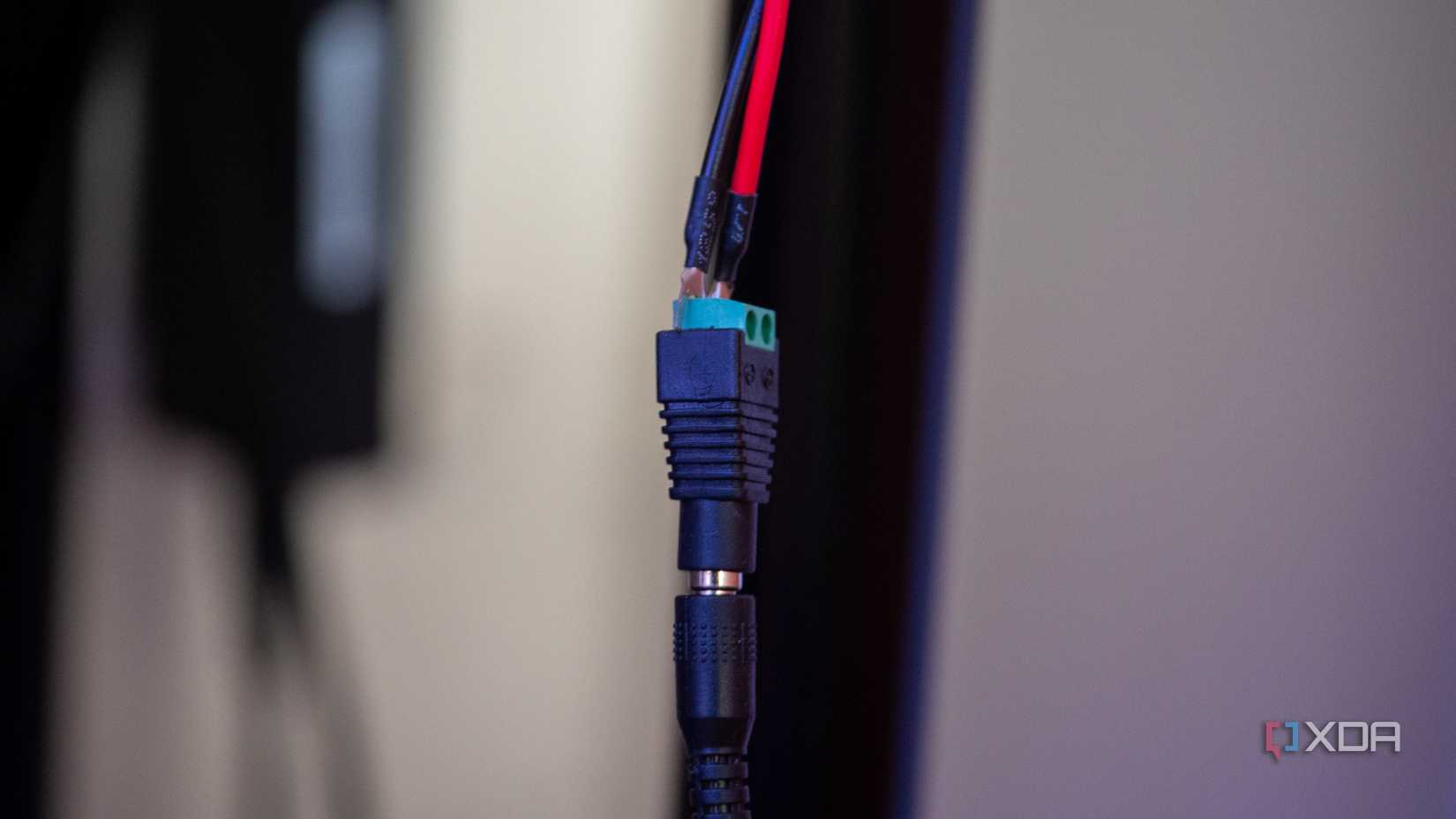
Finally, keep in mind that you’ll need a separate power source for the display and the controller. While I’ve seen some people state that an ESP32 can be powered from the same power source as the display (I’m using the Waveshare 5V 4A DC jack for power), I haven’t figured out how that would be achieved in a safe way, without potentially frying the ESP32 with too high a current.
This particular panel came with everything I needed, though I replaced the HUB75 connector with my own jumper wires, as the one it came with resulted in poor connection quality. It came with a DC barrel jack to two-pin terminal block adapter, and a power cable that can connect to two displays at a time, alongside a separate HUB75 connector for the second port so that it can be connected to another display.
Setting up on the ESP32
RAM constraints, but a lot of functionality

The ESP32 may seem underpowered on the surface, especially when compared to the Raspberry Pi, but that isn’t actually the case. Despite having a slower CPU and significantly less RAM, the ESP32 benefits from its DMA capabilities offered by the SPI master driver, which means that you don’t need to use the CPU for directly controlling the display at all. The original ESP32, ESP32-S2, and ESP32-S3 are all supported here.
With this configuration, you are largely constrained by memory usage. According to the calculator found on the ESP32-HUB75-MatrixPanel-DMA GitHub, the ESP32 I’m using here can just about manage full 24-bit color depth with a 64×32 module. With 8-bit color instead, it’ll stretch to a single 128×64 panel. It’ll also manage to control up to four chained 64×32 panels, assuming that they’re using 8-bit color as well.
For the ESP32-S3, you can enable PSRAM support, but it requires building the library with the appropriate build flag and isn’t recommended, especially in Q-SPI mode, as it’s too slow. With the original ESP32, I’m limited to roughly 200KB of SRAM once everything is loaded and running. It’s not a lot, and it’s significantly more constrained than the Raspberry Pi, but it does work.
My first issue that I ran into when configuring this was that the Wi-Fi sensitivity suddenly dropped off a cliff. While this is noted in the GitHub repository as affecting the ESP32-S3, I’ve never had any problem connecting to Wi-Fi on my ESP32 from my desk, as I’m right beside the router. However, with the panel connected, I had to move it even closer to my Wi-Fi source to get it to work. Unplugging it immediately brought back my connection, so if you’re planning on building one of these with an ESP32, be mindful of proximity to your access points.
I first experimented with ESPHome and discovered an external component wrapper for the HUB75 DMA library that allowed me to write basic code on the screen that would show information, like I would do in ESPHome as usual. This worked, and for basic stuff, it was a significantly easier way to get things running than what I ended up doing. Eventually, I turned to PlatformIO for my deployment. While it was a lot more “manual” of a process, there are a lot of examples out there to get things up and running. There are still some ESPHome examples you can find online, but not as many as you’ll find for the core library.

Through PlatformIO, I used the same HUB75 DMA library, and it was a lot more “native” in implementing it. I wrote all of my own code, like I did with the Raspberry Pi, and it mostly just worked. I created a page-based system, where I could again control it via MQTT, and pages would be cycled through with different information on them. I experimented with a clock on one page and a temperature page that pulled from my Zigbee2MQTT data in my MQTT broker.
This worked surprisingly well, and honestly, I think most people will be happy with this kind of project with one of these displays. Solder the ESP32 behind the display, put it in a case or a wooden box with the DC jack exposed (and a power source for the ESP32), and you have a neat little display that doesn’t take up much space and can sit on your desk. I wanted more, though, and the ESP32 can host web servers. I figured that someone had surely implemented this functionality before, so I did some research on what was available.
In my search, I found a few examples of exactly what I was looking for, including the MatrixCOS GitHub repository. It uses the same HUB75 DMA library to interface with the display and offers up a web portal that can be used to control the ESP32. It’s an operating system that’s command-oriented, complete with a web server that can take those commands and turn them into real outputs on the display. It seemed pretty great, but unfortunately, I couldn’t get it to work. Despite being recently updated, only one of the firmware files would boot, and Espressif’s own web-based flashing tool identified the others as potentially not being bootable.
Instead, I compiled it directly from source, and that worked, but I experienced a DMA-related crash once the ESP32 tried to invoke the display. This, coupled with other issues relating to Wi-Fi connectivity (my SSID has a space in it, which meant inputting my SSID through the serial input didn’t work as it delimits user inputs via spaces), meant that it was a non-starter. Even if I could get around the SSID issue, which I did through its fallback hotspot, the display is kind of the whole point.
After throwing in the towel on that front, I came across the Pixel Art Display repo on GitHub. It’s a similar project to MatrixCOS, though with fewer options, but it can also run on the ESP32. It offers local file storage for images and GIFs, and you can manage this storage from the web panel once you’ve got it connected. The web server is the main thing that I wanted anyway, as it means that someone can build one of these and manage their display from their computer rather than needing to connect directly to the ESP32 every time they want to make a change.
That particular project is built for a 64×64 display, and while you can modify the values that instantiate the display to fit a 64×32 panel instead, I still had to undergo extensive work in the source code to modify how GIFs are played and text is shown, as those are hard-coded to X and Y coordinates that fit a 64×64 panel. I also swapped the G and B pins for proper color output, as I initially forgot and had the same weird color issues that I had mentioned previously. Modifying the source code is also required if you want it to connect to your network, as you need to compile and flash it with your SSID and password.

Once I swapped everything out, though, it worked. GIFs played, text would scroll across the screen, and the clock worked too. I could upload new media from my web browser, click play, and it would immediately show up on the screen. It doesn’t resize GIFs for you, though, so you’ll need to manually do that to match your display size before uploading them.
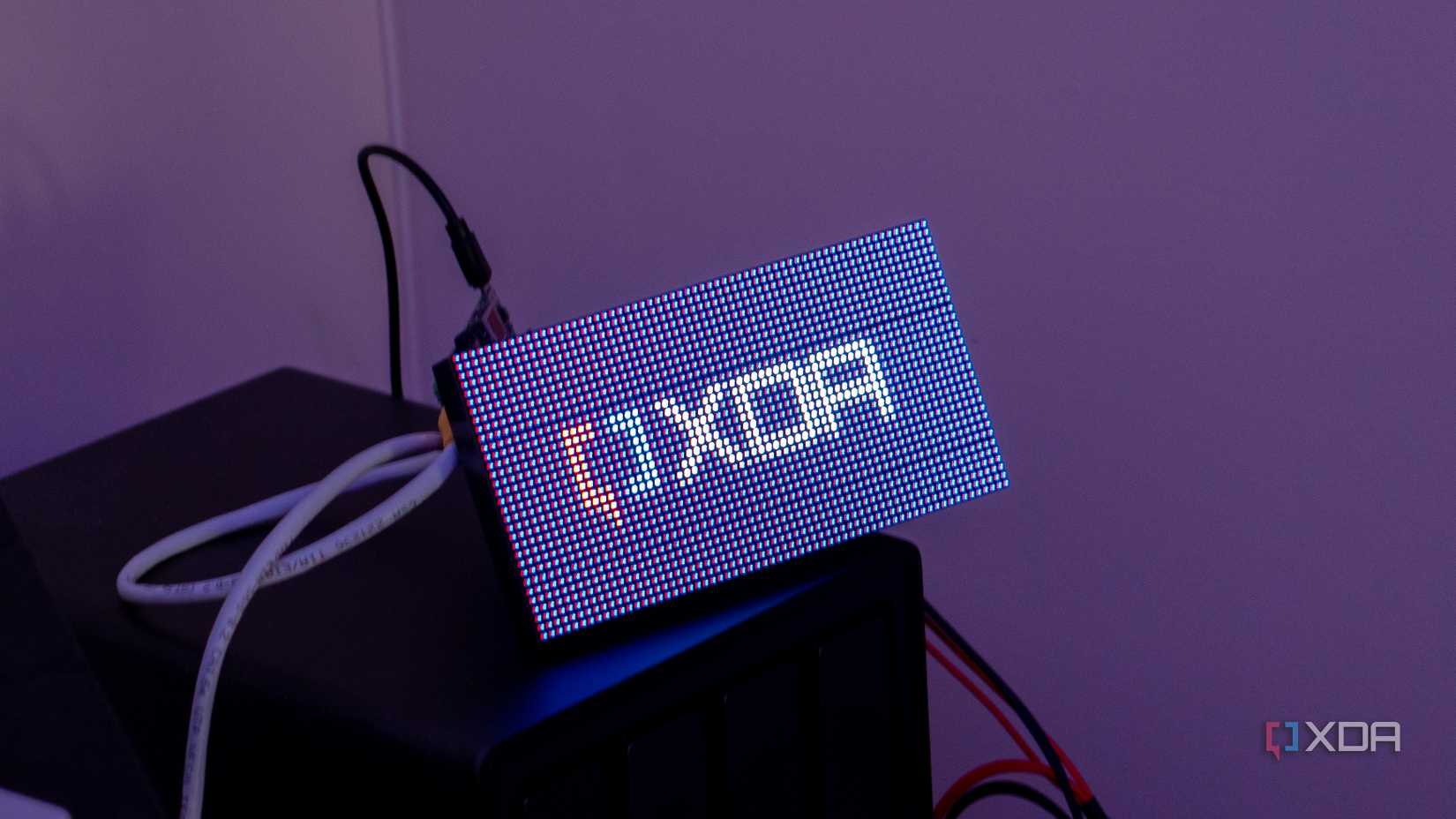
Something interesting with this setup is that, while there is no noticeable flickering, my camera really struggled to get a decent picture. Remember how I said that these displays refresh fast enough that the human eye can’t discern when the pixels are actually switched off? A camera with a fast enough shutter speed can, and while this was a mild issue when connected to the Raspberry Pi, it was way harder to get a photo when connected to the ESP32. This suggests the refresh rate is a lot lower than the Pi puts out. From looking at the ESP32 DMA code, it appears that the minimum refresh rate requested by default is 60Hz; not enough for a human to notice, but enough to make a camera struggle.
Setting up on the Raspberry Pi
Surprisingly easy, even with a weaker model
On my Raspberry Pi, the setup with the rpi-rgb-led-matrix API was surprisingly simple. Download the Git repository and build it, and you’ll be able to run most of the examples and prebuilt utilities out of the box to get to grips with its capabilities. These examples range from image renderers, animation playback, clocks, and more. Once you’ve built the codebase, you can use the built libraries in your own code, taking the pain out of interfacing with it directly over GPIO.
Developing for the Raspberry Pi has a number of issues here, and I came across them mainly out of reluctance to compile directly on my original Raspberry Pi. As it turns out, cross-compiling code for Armv6 is difficult, requires jumping through a lot of hoops, and ultimately ends in pain and suffering. Instead, I opted to code on my main PC and use basic syntax highlighting in VS Code to ensure I had everything else right. Anything relating to libraries couldn’t be checked and would throw errors, but I could ensure that the rest looked good.
The plan was to develop a simple way to display information on the screen, and as already mentioned, I used MQTT for this. I already use MQTT for Home Assistant anyway, so adapting the setup was trivial for controlling the display. I have an MQTT topic called “matrix”, and under it, I can publish Spotify data with the track and the artist alongside the current weather conditions. Then it’s just a matter of using my Raspberry Pi to connect to the MQTT server, pull data, and then process it for displaying on the screen.

Surprisingly, this didn’t turn out to be too difficult, and I expected to run into more issues than I did. The API libraries made things a lot simpler, though I am still sad that I wasn’t able to use Python for this. I wrote a basic MQTT client that runs in a separate thread, stores the responses locally, and draws them to the display. When the text is longer than the screen will allow for (in the case of the currently playing track and artist), it will scroll using the offscreen function of the RGB matrix library.
As well, I also draw ASCII art to the screen for the weather icons, though these need a lot of work. I’m mapping them from the Home Assistant-style weather conditions that go to MQTT to icons that can be drawn on the screen using ASCII, and this saves on resources as I don’t need to include images for decoding, processing, and conversion. As a result, each image works out to be 16×16 24-bit sets of pixels, totaling 768 bytes of memory per image. 16×16 is a bit too large and can cause icons to overlap with text at times, though it should be trivial to decrease this.
There’s a lot you can do with this, though, and it’s not limited to displaying text on the screen, despite the example shown above. While it’s great as an informational dashboard, it can be used to show pictures and GIFs, as I’ve shown in the pictures here. With a bit of work, you could even use it as a carousel of images taken from your locally hosted library, such as Immich.
With a more powerful Raspberry Pi, I would find it significantly easier to get creative with it. However, the code I’ve provided shows how much extra care is needed to provide a memory-safe environment (somewhat, I know of a few issues related to buffer sizes and such that I spotted when writing this article), and there are still many more things that would ideally be done to make it an even more robust piece of code. Still, as a proof of concept, it works very well, and the efficiency of C++ means that you can actually do a lot more with this display than you’d initially think with underpowered hardware like I’m using here.
This was an intense project
And it’s certainly not for beginners
I love development, and building my own sensors and smart home devices is a fun hobby that I’ve enjoyed immensely. Yet, this project was undoubtedly a slog at times. When it came to the ESP32, the DMA library is fantastic, and getting it up and running with my own code was surprisingly simple thanks to the sample code provided on the library’s GitHub. However, once it comes down to doing more, like hosting a web server, RAM constraints really kick in.
As for the Raspberry Pi, with a more modern model, it’s likely that things would have been significantly simpler. Even still, it’s kind of amazing that both of these devices, underpowered in their own ways, can drive a display like this perfectly when configured right. If you want to try it out for yourself, the code for all of these projects is on my GitHub, including the YAML that I wrote for testing this with ESPHome.
The Waveshare 64×32 is a beautiful panel that looks great anywhere, and I’ll likely turn it into a bit of an arts and crafts project to get it in some kind of permanent housing, ready to be placed on a desk, bookshelf, or maybe even wall mounted. The end result is fantastic, and I absolutely love how it looks. It was a lot of work, but honestly, I think that’s part of the appeal in a way. I love learning new things, and projects like this are a great way to do that. I’m probably going to give ESPHome another go, or develop my own C++ implementation further and deploy a web server inside of it.
No matter what approach I take from here, I’m sure future experiences with other hardware will be a little bit easier now, thanks to this one, and I’m really happy with my shiny, new, and beautiful-looking display that I can proudly point to and say, “Yeah, I developed that.”